


Observatory dome controller
Dome rotation controller hardware
This controller use an ESP32 Dev kit (future version might use the ESP32S3) with an Ethernet port using WIZnet W5500 and a standard XT60 connector for the power.
It uses a local WiFi connection to the Shutter controller communication.
It runs its own ASCOM Alpaca server.
Rotation controller features :
- 12V powerpole power input.
- Ethernet connection.
- USB serial connection (using ESP32 programming port).
- Fully upgradable using the Arduino IDE.
- Ability to change the local WiFi SSID for location with multiple domes.
- Can drive stepper driver or servo drive that use the standard 3 signals: Enable, Direction and Step.
- Has a calibration procedure to allow it to work on any dome size.
- Inputs for weather event shutter auto close (AAG, Hydreon RG-11, ..).
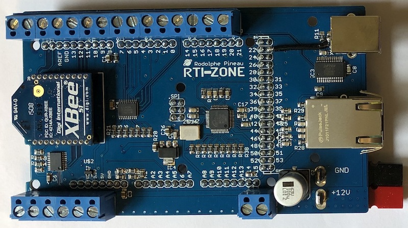
Here is a photo of the current rotation controller :
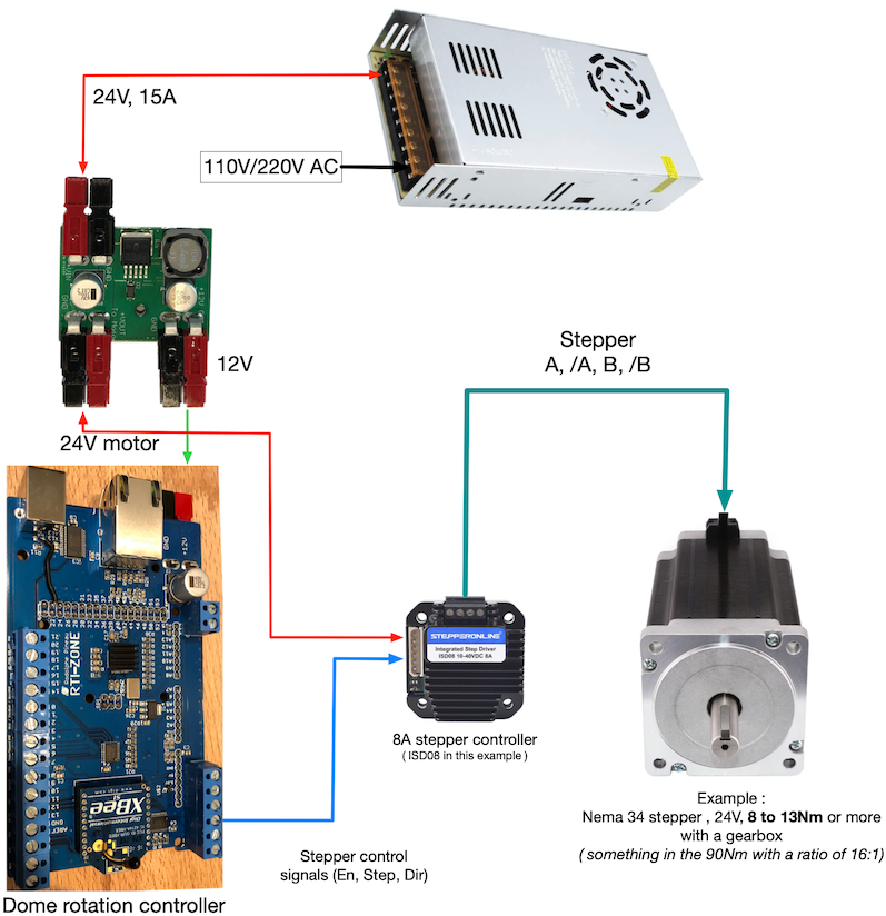
The dome controller is meant to be used on dome like Nexdome, Explora Dome, any dome that can me moved by a good stepper motor, assuming you get the track and the cogwheel or gear from the manufacturer. In all case, make sure to get a motor with a good torque and a gearbox on it. If your dome is on the heavy side, I would recommend something in the 9 to 12 Nm torque with at least a 15:1 gearbox on it, powered at 24V or 48V with 4 to 8 Amps (this usually requires the use of larger NEMA 34 motors and gearbox). When choosing a motor and gearbox make sure the output shaft can be used on the gear you'll get. The NexDome and Explora Dome gear (or cogwheel) have a 12mm shaft hole (aka bore) on their hub. A lot of gearbox come with a 14mm and 16mm shaft so some adaptation might be required (enlarging the hole with a drill press, changing the gear hub)
As more people test this on their own dome and get new ways of getting a track and motor on them I'll build a list of motor, gear, track vendors ...
This has been tested with the original Nexdome stepper driver (TB6600) as well as some DMT stepper driver from StepperOnline (I use a StepperOnline DMT556T with a 24V power supply).
Depending on what stepper driver you use, you can set the proper level for the enable signal in the firmware (HIGH or LOW) to ensure that when disabled the stepper driver doesn't draw any current.
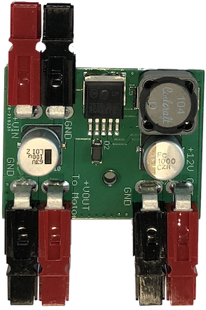
Do not apply more that 16V to the board power input as this would damage the switching regulator on the board. If you need to power the motor with 24V or 48V power supply, see my power adapter bellow. The default settings work for the TB6600 and DMT stepper drivers
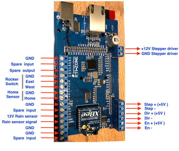
Here is the wiring diagram for the current version :
Dome shutter controller hardware
The shutter shield is a lot simpler as it only need to connect to the rotation controller over the wireless link using the onboard WiFi.
Shutter controller features :
- 12V XT60 power input
- Fully upgradable using the Arduino IDE
- Can drive any stepper driver or servo drive that use the standard 3 signals: Enable, Direction and Step.
- Support for dual shutter system (require a Cytron MD13S or MDD10A to drive linear actuator(s) for the bottom drop out shutter). Not implemented yet in the current firmware (hardware is ready for it)
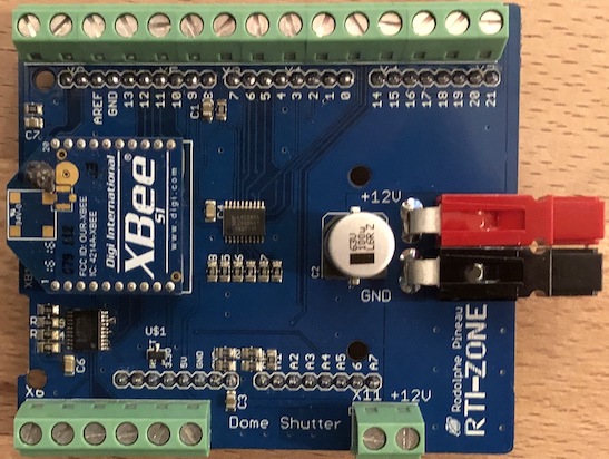
Here is a photo of the current shutter controller shield prototype :
The stepper driver type is configurable in the same way as the rotation controller (HIGH or LOW for Enable) in the firmware.
In addition to the 2 limit switch input for the main shutter, 2 inputs are wired for future use (like open/close sensor for a drop-out shutter) as well as 2 outputs (to potentially control Cytron MD13s to open/close a dropout shutter using a linear actuator).
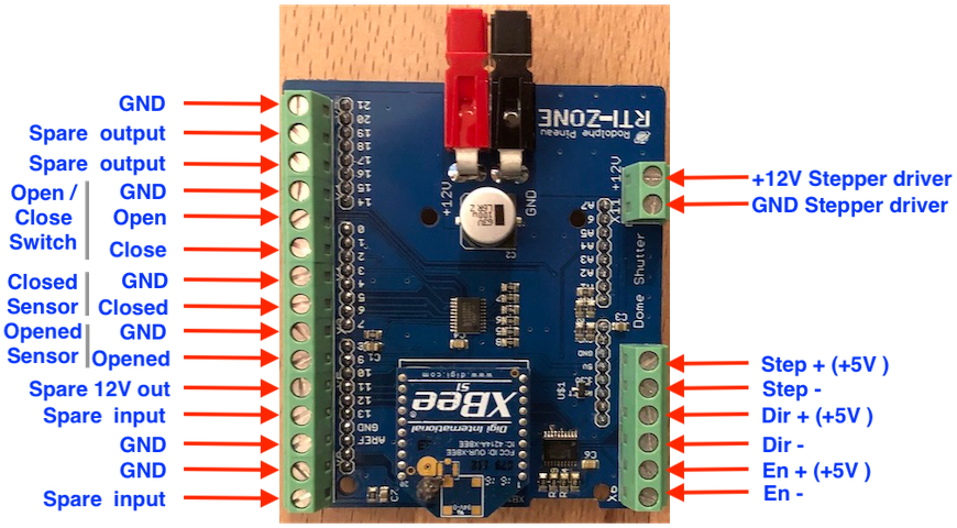
Here is the wiring diagram :
PCB file and components
All the PCB files are in the git repo ( PCB files ) . I use Autodesk Fusion to make the PCB.
There is also CSV files in the repository with all the components and manufacturer part number. As some component might be out of stock you can replace them with equivalent ones from other brands (mostly resistors, capacitors and buffers).
Controllers firmware
You can find the firmware on my github repo : RTI-Dome Firmware
By default the rotation controller network configuration is set to use DHCP. If no DHCP server is available, it will default to 192.168.1.9 with a netmask of 255.255.255.0 and set its default gateway to 192.168.1.1 after about a minute. The TCP port is 2323. Only one connection is allowed at a time over TCP to avoid conflict.
The USB serial connection is set to 115200 bauds (115200 8N1).
The default SSID is set to RTIShutter. If the rotation controller is already connected to a shutter controller, when you change it, the new SSID will send to the shutter controller, reconfigure itself while the shutter controller does the same, then reconnect using the new SSID. This is useful if you have more than one set of controllers close to each other (multiple domes). If you plan on having more than one set, I would recommend that you change the SSID even on the first one before setting the others (aka you only have one for now but plan on having more).
All settings are saved to the ESP32 NVS on both controllers.
Controllers Commands documentation : rti-dome-commands.pdf
Dome controller software
As I mostly do X2 PlugIns for TheSkyX, that's the only supported application for now via a new X2 plugin : RTI-Dome X2 plugin
The controller also has a full Alpaca server onboard.
To do list
Here is a quick list of things I'd like to add or change to the current firmware and hardware :
- Add support for drop out shutter. The hardware is there, I need to add the code to the shutter firmware to control linear actuators with a Cytron MD13S or MDD10A (or something similar).
- If we can design some type of power bus/ring to power the upper part of the dome, we could get rid of the whole battery system (like the new NexDome track on more recent dome)
- Add an option to operate the shutter at park only so that it connects to some power pads and is only powered at this position. This is another way to not have the battery on the upper dome. This might already work but need testing.
- Make a firmware version for Roll-off Roof.
All pictures and/or material on this page is the property of Rodolphe Pineau. Unauthorized use and/or duplication of this material without express and written permission from the author and/or owner is strictly prohibited.